青岛谁家做网站百度推广登录账号首页
天地图开发的优点
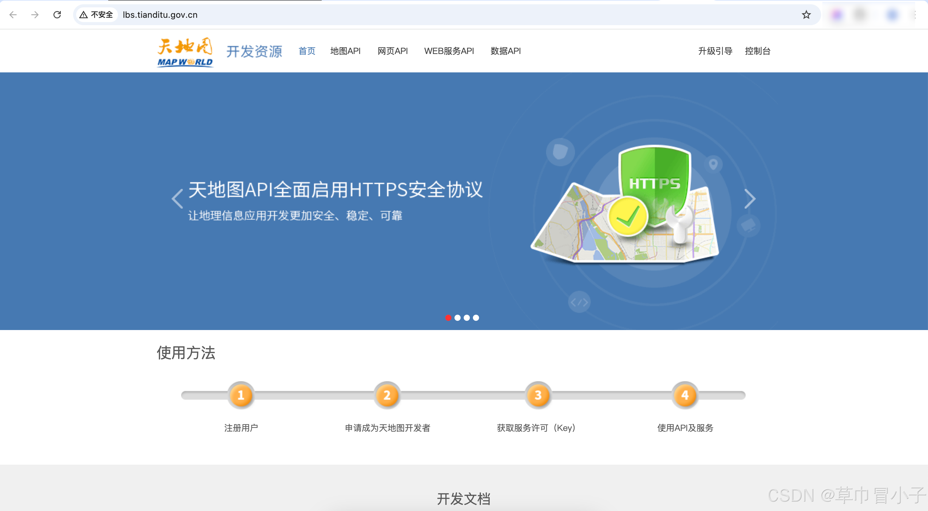
天地图作为国家地理信息公共服务平台,与百度地图、腾讯地图、高德地图等商业地图平台相比,具有以下显著优势和特点:
1. 官方权威数据,精度更高
- 国家基础地理信息:直接来源于国家测绘部门,数据权威性最高
- 行政区划最准确:国界、省界等行政边界完全按照国家标准绘制(尤其适合政务、科研等严肃场景)
- 更新机制规范:定期由国家测绘部门统一更新,数据质量有保障
2. 完全免费,无商业限制
- 0成本使用:所有API和服务完全免费(商业地图的高级功能通常收费)
- 无调用配额限制:基础服务无严格QPS限制(商业地图免费版通常有严格限制)
- 无强制品牌露出:不要求强制添加"Powered by"标识
3. 专业GIS能力突出
- 坐标系标准:默认采用CGCS2000国家大地坐标系(商业地图多为GCJ-02加密坐标系)
- 地形服务:提供DEM数字高程数据、等高线等专业地形数据
- 三维地形:支持真实地形渲染(非简单3D建筑物模型)
4. 政务领域优势明显
- 涉密处理合规:已通过国家测绘保密处理,可直接用于政务系统
- 行政区划工具:提供标准的行政区划查询接口(含乡镇级)
- 自然资源数据:集成地质、气象等部委专业数据
5. 特殊场景支持
- 历史地图:提供不同年份的历史地图对比
- 矢量切片:支持自定义矢量地图样式
- 专业图层:提供地质灾害、气象云图等专业图层
对比表格
| 特性 | 天地图 | 商业地图(高德/百度等) |
|---|---|---|
| 数据来源 | 国家测绘局 | 自采+第三方 |
| 坐标系 | CGCS2000 | GCJ-02(火星坐标) |
| 边界准确性 | 国家官方标准 | 部分调整 |
| 收费模式 | 完全免费 | 基础免费/高级收费 |
| 调用限制 | 较宽松 | 严格配额 |
| 三维地形 | 真实地形 | 建筑物3D模型 |
| 政务合规性 | 完全合规 | 需额外审批 |
适用场景建议
- 必选天地图:政务系统、科研论文、国土规划、军事相关、教育用途
- 推荐商业地图:ToC商业应用、实时路况、O2O服务、需要丰富POI数据的场景
需要注意的不足
- POI数据丰富度 不如商业地图(餐饮/商铺等生活信息较少)
- UI体验 相对传统,交互设计较保守
- 生态支持 第三方插件和社区资源较少
天地图特别适合需要权威性、专业性、合规性的场景,是国家空间基础设施的重要组成部分,而商业地图在用户体验、生活服务、实时数据方面更具优势。开发者可根据实际需求选择或组合使用。
以上总结仅供学习参考,更多详细请关注天地图官方网站数据更新为准。
完结。